Bandwidth reduction FOS
Microphone amplifier with AGC

Scheme of the resonant amplifier on K174PS1

The frequency range 0.2 ... 200 MHz is determined by the choice of circuit L. The transmission coefficient is not less than
20 dB. AGC depth not less than 40 dB.
S-meter with LEDs
Connect the S-meter to the ULF input, to the volume control. The setting consists in replacing the resistors R9 and R10 with one trimmer, to clarify the ratings of this divider.


LPF for a transistor power amplifier of a HF radio station
The proposed low-pass filter works in conjunction with a transistor power amplifier in the frequency range from 1.8 to 30 MHz with an output power of not more than 200 watts.
The low-pass filter inductors are frameless and are wound turn to turn with PEV-2 wire with a diameter of 1.2 mm for bands 14; 18; 21; 24.5; 28 MHz and wire PEV-2 with a diameter of 1.0 mm - to the rest. The ratings of capacitors C1, C2, C3, which do not fall into the standard series, must be selected from several capacitors in parallel or series connection.

Structurally, the low-pass filter is made on a three-section ceramic biscuit switch 1 type 11P3N in the form of a single one, enclosed in a shielding case made of non-magnetic material. Copper bus 2 is a common low-pass filter wire and is connected
electrically with chassis 3, radio chassis and ground bar. The middle biscuit of the switch - supporting - for mounting the filter elements. At the input and output of the low-pass filter, coaxial connectors of the SR-50 type are installed.
I. Milovanov UY0YI
Range selector
Transistor emitters are loaded on the range switching relay
Q-multiplier for a simple receiver
A prefix that allows you to increase the sensitivity and selectivity of the receiver due to positive feedback without altering it.
The quality multiplier is an underexcited generator of electrical oscillations with positive feedback, the value of which can be changed. If the operating mode of the generator is chosen such that the compensation of active losses in the oscillatory circuit is incomplete, then self-excitation of oscillations will not occur, but the quality factor of the circuit will be very large. When such a circuit is included in the resonant amplifier of the receiver, the selectivity and sensitivity can increase tenfold. Most often, a Q-multiplier can be included in an intermediate frequency amplifier. The Q-multiplier itself is made as a separate structure with leads for connecting it to the receiver.

The tarannistor emitter current, which determines its amplifying properties, can be smoothly controlled by a variable resistor R2. When the emitter current is low, the effects of PICs are weak. With a gradual increase in the emitter current, the effect of the PIC is enhanced due to an increase in the amplifying properties of the transistor, and, finally, at a certain feedback value, the generator is excited. If the Q factor is brought to self-excitation, then it will work like a second local oscillator; in this case, the bandwidth of the mixer can reach 500 Hz or less. In this mode, the receiver can receive radio stations operating by telegraph. The LC and L1C1 circuits must be tuned to an intermediate frequency.
Crystal oscillator 500 kHz
In sports equipment, quartz oscillators are used at a frequency of 500 kHz. But it happens that a radio amateur does not have the necessary quartz. In this case, the crystal oscillator helps out, followed by division to the desired frequency. Your attention is invited to a diagram of such a device on the IC 4060 chip (generator and 14-bit counter)
The generator operates at a frequency of quartz (widely available) 8 MHz. The output signal has a frequency of 500 kHz. The output low-pass filter has a cutoff frequency of approximately 630 kHz and removes the first harmonic, resulting in a pure sine wave. The buffer amplifier is implemented on a bipolar transistor according to the "common collector" scheme.
GPA mixing type
V.Sazhin
Mixer-type GPA is designed for a transceiver with an intermediate frequency of 9 MHz. The tuning range of the master oscillator on the transistor VT1-5.0 ... 5.5 MHz. The RF voltage at the output of the source followers is about 2 volts. Equality of output voltages in different ranges is achieved by selecting the resistances of the resistors Rv connected in series with L2. The L2-L3 filters are set to the middle of the GPA operating range. Filters, like T1, are wound on ferrite rings VCh3 with a diameter of 10 mm.
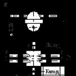
Frequency converter
The mixer shown in the diagram provides a wider dynamic range (compared to active mixers) and a very low noise level, which makes it possible to obtain high receiver sensitivity even without a preliminary URF. The output of the mixer uses a circuit tuned to the IF frequency.
It differs from the scheme proposed in [L.1] by the way in which a negative, relative to the sources, bias voltage is applied to the gates of transistors, which is necessary to obtain maximum sensitivity. Gates through the winding T1 are galvanically connected to a common minus supply. And the sources are supplied with a positive bias voltage from the tuning resistor R1. Thus, the gates are at a negative potential with respect to the sources. This method of supplying bias is beneficial for designs with a common minus, since it does not require an additional negative power source.
The RF transformer is wound on a ferrite ring with a diameter of 7 mm and a permeability of 100HN or 50VCH. Winding is carried out in three wires, 12 turns. One winding is used as "3", and "1" and "2" are connected in series (the end of one winding with the beginning of the other). For the transistors indicated in the diagram, the optimal bias voltage is 2.5 V (set to the maximum sensitivity) and the local oscillator voltage level is 1.5V. Transistors are applicable KP302,303,307 with the lowest cutoff current. Several better parameters can be achieved with KP305 transistors.
The mixer is reversible and can be successfully used in a transceiver.
A variant of the circuit using EMF is shown in Fig. 2.
Literature
1. V. Polyakov B. Stepanov
LO receiver mixer
Radio No. 4 1983
Switch mode "reception / transmission"
LO receiver mixer
V. Besedin UA9LAQ
An article with this title was published in . It describes the mixer.on field-effect transistors used as controlled resistances.The mixer circuit shown in is made on a matched pair
FETs with n-channel and receives a bias from the sourcenegative voltage bipolar power supply. Such foodquite cumbersome for a receiver, especially a portable one. Currentlyequipment with a unipolar source has become widespreadpower supply with a "grounded minus".

To adapt the mixer to modern realities, I propose to replace transistors V1 and V2 with a transistor assembly of the K504 series. In this case, we have an identical pair of p-channel transistors, the gates of which are positively energized through the trimmer resistor R1.
The research conducted by the author showed that this assembly works satisfactorily even at frequencies of the 2-meter range (144–146 MHz), but the receiver with such a mixer on VHF is somewhat “blunt”. However, the author used this mixer in the VHF FM superheterodyne receiver at 145.5 MHz for the local VHF network TRAN. The frequency of the quartz local oscillator is 67.4 MHz, the intermediate frequency of the receiver is 10.7 MHz. A high-frequency amplifier based on a KT399A transistor helped to achieve a receiver sensitivity of a few microvolts.
Since the field-effect transistors of the assembly require bias to "close" them, using the data from, you can select an instance of the assembly for the receiver supply voltage. In addition, the field-effect transistors in the K504NTZ and K504NT4 assemblies are quite powerful, which can positively affect the dynamic characteristics of the receiver.
This circuit has a simple switching of ranges (switching coils), has enhanced stabilization of the generation mode and shows very decent stability. It was planned as a GPA at IF = 5 MHz, and so the stability at 24 MHz was very decent (about 200 Hz per hour). In general, at the indicated ratings, it continuously covers the range from 6.7 to 35 MHz with an amplitude unevenness of not more than 6 dB
If you liked the page - share with your friends:
To increase the sensitivity of radio receivers - radios, televisions, various high-frequency amplifiers (UHF) are used. Connected between the receiving antenna and the input of a radio or television receiver, such UHFs increase the signal coming from the antenna (antenna amplifiers). The use of such amplifiers allows you to increase the radius of reliable radio reception, in the case of receivers as part of transceivers (radio stations), it allows you to increase the operating range, or, while maintaining the same range, reduce the radiation power of the radio transmitter.
On fig. 1 shows a diagram of a broadband UHF on a single transistor connected according to a common emitter (CE) circuit. Depending on the transistor used, this circuit can be successfully applied up to frequencies of hundreds of megahertz. The values of the elements used depend on the frequencies (lower and upper) of the radio band.
Transistor stages connected according to the common emitter (CE) circuit provide relatively high gain, but their frequency properties are relatively low.
Transistor stages with a common base (CB) have less gain than transistor stages with OE, but their frequency properties are better. This allows you to use the same transistors as in OE circuits, but at higher frequencies.

- Coil L1 - frameless Ø4 mm contains 2.5 turns of PEV-2 wire with a diameter of 0.8 mm.
- Inductor L2 - RF inductor 25 μH.
- Choke L3 - RF choke 100 uH.
- Transistors KT3101, KT3115, KT3132…
The amplifier is mounted on a double-sided fiberglass in a hinged way, the length of the conductors and the area of the contact pads should be minimal. When repeating the scheme, it is necessary to provide for careful shielding of the device.
If you liked the post, share it with your friends in social bookmarks below...
The more I get to know the modern element base, the more I am surprised at how easy it is to make such electronic devices now that you could only dream of before. For example, the antenna amplifier, which will be discussed, has an operating frequency range from 50 MHz to 4000 MHz. Yes, almost 4 GHz! In the days of my youth, one could simply dream of such an amplifier, and now even a novice radio amateur can assemble such an amplifier on one tiny microcircuit. Moreover, he does not have experience with super-high-frequency circuitry.
The antenna amplifier presented below is extremely easy to manufacture. It has good gain, low noise and low current consumption. Plus a very wide range of work. Yes, it's also small enough to fit anywhere.
Where can I use a universal antenna amplifier?
Yes, almost anywhere in a wide range of 50 MHz - 4000 MHz.- - As a TV antenna signal amplifier for receiving both digital and analog channels.
- - As an antenna amplifier for an FM receiver.
- - others
Characteristics of the antenna amplifier
- Operating range: 50 MHz - 4000 MHz.
- Gain: 22.8 dB - 144 MHz, 20.5 dB - 432 MHz, 12.1 dB - 1296 MHz.
- Noise figure: 0.6dB - 144MHz, 0.65dB - 432MHz, 0.8dB - 1296MHz.
- The current consumption is about 25 mA.
The low-noise amplifier performed very well. The low current consumption justifies itself.
Also, the microcircuit perfectly withstands high-frequency overloads without loss of performance.
Antenna amplifier manufacturing
Scheme
The circuit uses an RFMD SPF5043Z chip, which can be bought at -.In fact, the whole circuit is an amplifier chip and a filter for its power supply.
amplifier board

The board can be made from foil textolite, even without etching, as I did.
We take a two-sided foil textolite and cut out a rectangle about 15x20 mm in size.

Then, with a permanent marker, draw the wiring along the ruler.


And then you want to poison, but you want to cut the tracks mechanically.

Next, we tin everything with a soldering iron and solder SMD elements of size 0603. We close the lower side of the foil board to a common wire, thereby shielding the substrate.


Setup and testing
Tuning is not required, you can of course measure the input voltage, which should be within 3.3 V and the current consumption is approximately 25 mA. Also, if you are working in the range above 1 GHz, then you may need to match the input circuit by reducing the capacitor to 9 pF.We connect the board to the antenna. The test showed good gain and low noise.

It will be very good if you place the board in a shielded case, such as this.

You can buy a ready-made amplifier board at, but it costs several times more than a microcircuit separately. So it is better to be confused as it seems to me.

Schema completion
To power the circuit, a voltage of 3.3 V is required. This is not very convenient, for example, if you use an amplifier in a car with an on-board network voltage of 12 V.
For these purposes, a stabilizer can be introduced into the circuit.
Connecting the amplifier to the antenna
By location, the amplifier should be located in close proximity to the antenna.To protect against static and thunderstorms, it is desirable that the antenna be closed to direct current, that is, you need to use a loop or frame vibrator. Antenna type "" would be a great option.
We make a frame active antenna for simple shortwave radios.
Is it possible to listen to the broadcast for people who do not have space to install large, full-size antennas? One of the outputs is a loop active antenna mounted directly on the table, near the radio.
The practical manufacture of such an antenna will be discussed in this article ...
So, a small-sized active loop antenna is an antenna consisting of one or more turns of copper wire (tube) or even a coaxial cable. There are plenty of examples of such antennas on the web.
I made my antenna in the form of a vertical structure, which is installed on a table near the radio. The loop active antenna is a kind of large inductor, made of copper wire with a diameter of 1.2 mm and contains four turns. The number of turns is chosen at random)). The diameter of the manufactured loop antenna is approximately 23 cm:

To reduce its own capacitance, the turns of the antenna are wound with a pitch of 10 mm. To maintain the constancy of the winding pitch, as well as to give the entire structure the necessary rigidity, intermediate spacers made of fiberglass 2 mm thick were used. The sketch of the spacers is shown below: 
This is what the intermediate spacer in the antenna looks like:

To give stability to all this design, support posts are used, also made of fiberglass, and which serve as antenna legs: 
The copper wire is threaded into the appropriate holes in the spacers and posts, and fixed in them with a drop of cyanoacrylate glue.
This is how the rack looks like in a manufactured copy of the antenna:

General view of the manufactured antenna:

For the sake of interest, I connected the manufactured loop antenna to the AA-54 antenna analyzer.
The antenna's own resonance was found at a frequency of 14.4 MHz.
In the photo below, the display of the AA-54 antenna analyzer at the time of measuring the parameters of the loop antenna at the resonance frequency:

As you can see, the antenna impedance at a frequency of 14.4 MHz is 13.5 ohms, the active resistance is 7.3 ohms, the reactance is relatively small - minus 11.4 ohms and is capacitive in nature.
The inductance of the loop antenna (and it, in fact, is an inductor) was 7.2 μH.
This is all that concerns the manufacture and parameters of the loop antenna itself.
But, since the antenna is active, it means that it also contains an antenna amplifier.
When choosing an antenna amplifier circuit, I was guided by the principle of choosing something not too abstruse and complex, and easy to manufacture.
Google, as always, dumped a mountain of schemes)) Without hesitation, I chose one of them, which seemed interesting to me.
The circuit of this antenna amplifier was published somewhere else in the early 2000s in one of the foreign magazines. This amplifier seemed interesting to me from the point of view that it has a balanced input - just right for my loop antenna.
Schematic diagram of the antenna amplifier:

In the original, transistors of the BF series were used in this amplifier - something like BF4 **.
These were not available, so I assembled an amplifier from what was at hand - 2N3904, 2N3906, S9013.
Actually, the amplifying stage is assembled on VT1VT2 transistors. An emitter follower is assembled on the VT3 transistor to match the high output impedance of the amplifier with the relatively low input impedance of radio receivers.
The amplifier is powered by a voltage of 6 V. The operating modes of the transistors are set by selecting the resistor R3. The voltages at the electrodes of the transistors are indicated in the diagram.
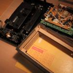
The amp worked almost immediately. I tried to install transistors KT315, Kt361 in this amplifier, but its efficiency immediately deteriorated noticeably, so I refused this option. I assembled the antenna amplifier on the circuit board, but I also prepared a printed circuit board for it:

As a receiver for field tests of an active loop antenna with an amplifier,
By connecting the output of the antenna amplifier to the input of the receiver and turning on the power, I immediately noticed an increase in the noise level. This is not surprising - the antenna amplifier contributes ...
The last stage of testing was to connect the actual loop antenna to the input of the antenna amplifier and try to receive any signals from the air..
And it succeeded! Many stations working with single-sideband modulation on the 40 m band are well audible. It is clear that the stations are not heard as loudly as on a full-size antenna. Yes, and you can not compare a normal antenna with a loop antenna located next to the receiver. Also, during the operation of an active loop antenna, a slightly increased noise level is observed. You need to put up with this - this is a fee for small size. It is also desirable to place such an antenna away from all kinds of interference sources - charging, energy-saving light bulbs, network equipment, etc.
conclusions: such an antenna quite has the right to life, it receives a lot of stations. For those who do not have the opportunity to hang a large, long antenna, this can be a way out of the situation.
Video demonstration of the operation of a loop active antenna on the 7 MHz band:
The frequency range of 1-30 MHz is traditionally called shortwave. On short waves, you can receive radio stations located thousands of kilometers away.
Which antenna to choose for shortwave reception
No matter which antenna you choose, it is best that it be external(on the street), the most highly located and was away from power lines and a metal roof (to reduce interference).
Why is an outdoor antenna better than indoor? In a modern apartment and apartment building there are many sources of electromagnetic fields, which are such a strong source of interference that often the receiver receives only interference. Naturally, an external antenna (even on a balcony) will be less affected by these interferences. In addition, reinforced concrete buildings shield radio waves, and therefore the useful signal will be weaker indoors.
Always use coaxial cable to connect the antenna to the receiver, this will also reduce the level of interference.
Receiving Antenna Type
In fact, on the HF band, the type of receiving antenna is not so critical. Usually a wire 10-30 meters long is enough, and the coaxial cable can be connected in any convenient place on the antenna, although to provide more broadband (multi-band), it is better to connect the cable closer to the middle of the wire (you get a T-antenna with shielded reduction). In this case, the braid of the coaxial cable is not connected to the antenna.
Although more long antennas can receive more signals, they will also receive more interference, which ultimately equalizes them with short antennas. In addition, long antennas overload (there are "phantom" signals over the entire range, the so-called intermodulation) household and portable radios with strong radio signals, due to the fact that they have a small dynamic range, compared to amateur or professional radios. In this case, the attenuator must be turned on in the radio receiver (switch to the LOCAL position).
If you are using a long wire and connecting to the end of the antenna, it would be better to use a 9:1 matching transformer (balun) to connect the coaxial cable, because. the “long wire” antenna has a high active resistance (of the order of 500 ohms) and such matching reduces the losses on the reflected signal.

Matching transformer WR LWA-0130, ratio 9:1
active antenna
If you do not have the opportunity to hang an external antenna, then you can use an active antenna. active antenna- this is, as a rule, a device that combines a loop antenna (or a ferrite or telescopic one), a broadband low-noise high-frequency amplifier and a preselector (a good active HF antenna costs over 5,000 rubles, although it makes no sense to buy an expensive one for household radios, something like Degen DE31MS). To reduce interference from the mains, it is better to choose an active battery-powered antenna.
The point of an active antenna is to suppress interference as much as possible and amplify the useful signal at the RF (radio frequency) level without resorting to conversions.
In addition to the active antenna, you can use any indoor antenna that you can make (wire, frame or ferrite). In reinforced concrete houses, the indoor antenna should be located away from the electrical wiring, closer to the window (preferably on the balcony).
Magnetic antenna
Magnetic antennas (frame or ferrite), to one extent or another, under favorable circumstances, can reduce the level of "urban noise" (or rather, increase the signal-to-noise ratio) due to their directional properties. Moreover, the magnetic antenna does not receive the electrical component of the electromagnetic field, which also reduces the level of interference.

By the way, EXPERIMENT is the basis of amateur radio. External conditions play a significant role in the propagation of radio waves. What works well for one radio amateur may not work at all for another. The most illustrative experiment on the propagation of radio waves can be carried out with a television decimeter antenna. Rotating it around the vertical axis, you can see that the highest quality image does not always correspond to the direction to the television center. This is due to the fact that during propagation, radio waves are reflected and “mixed with others” (interference occurs) and the most “high-quality” signal comes with a reflected wave, and not with a direct one.
grounding
Don't forget about grounding(through the heating pipe). Do not ground the radio to a protective conductor (PE) in the socket. Old tube radios especially “love” grounding.
Izoshutka
Fighting radio interference
In addition to everything, to deal with interference and overloads, you can use preselector(antenna tuner). Using this device allows you to suppress out-of-band interference and strong signals to a certain extent.
Unfortunately, in the city, all these tricks may not give the desired result. When you turn on the radio, only noise is heard (as a rule, the noise is stronger in the low frequency ranges). Sometimes novice radio observers even suspect their radios of malfunction or unworthy characteristics. Checking the receiver is easy. Disconnect the antenna (fold the telescopic antenna or switch to an external one, but do not attach it) and read the S-meter. After that, extend the telescopic antenna or connect an external one. If the S-meter reading has increased significantly, then everything is in order with the radio, and you are out of luck with the reception place. If the interference level is close to 9 points or higher, normal reception will not be possible.
Alas, the city is full of "broadband" interference, i.e. sources generate electromagnetic waves of a wide spectrum. Typical representatives: switching power supplies, collector motors, cars, cable TV and Internet networks, Wi-Fi routers, ADSL modems, industrial enterprises and much more.
The easiest way to "search" for the source of interference is to survey the room with a pocket radio (no matter what band, LW-MW or HF, just not the FM band). Walking around the room, you can easily notice that in some places the receiver makes more noise - this is the “location” of the interference source. “Noisy” will be almost everything connected to the network (computers, energy-saving lamps, network wires, chargers, etc.), as well as the wiring itself.
It was in order to somehow reduce the harmful effects of urban interference that “super-duper” fancy radios and transceivers became popular. An urban radio amateur simply cannot work comfortably on household equipment that shows itself worthy “in nature”. Greater selectivity and dynamics are required, and digital signal processing (DSP) allows you to "work wonders" (for example, suppress tonal noise) that analog methods cannot.
Of course, the best HF antenna is directional (wave channel, QUARD, traveling wave antennas, etc.). But let's be realistic. Building a directional antenna, even a simple one, is quite difficult and expensive.