RAID(English) redundant array of independent disks - redundant array of independent hard drives)- an array of several disks controlled by a controller, interconnected by high-speed channels and perceived by an external system as a single whole. Depending on the type of array used, it can provide varying degrees of fault tolerance and performance. Serves to increase the reliability of data storage and / or to increase the speed of reading / writing information. Initially, such arrays were built as a backup to storage media on random access (RAM) memory, which at that time was expensive. Over time, the abbreviation acquired a second meaning - the array was already made up of independent disks, implying the use of several disks, not partitions of a single disk, as well as the high cost (now relatively just a few disks) of the equipment needed to build this very array.
Consider what RAID arrays are. First, let's look at the levels that were presented by scientists from Berkeley, then their combinations and unusual modes. It is worth noting that if disks of different sizes are used (which is not recommended), then they will work according to the smallest volume. The extra volume of large disks will simply not be available.
RAID 0 Striped Disk Array without Fault/Parity (Stripe)
It is an array where the data is divided into blocks (the block size can be set when creating the array) and then written to separate disks. In the simplest case, there are two disks, one block is written to the first disk, the other to the second, then again to the first, and so on. This mode is also called "striping" because when data blocks are written, the disks being written to are interleaved. Accordingly, the blocks are also read one by one. Thus, I / O operations are performed in parallel, which leads to greater performance. If earlier we could read one block per unit of time, now we can do it from several disks at once. The main advantage of this mode is precisely the high data transfer rate.
However, miracles do not happen, and if they do, then infrequently. Performance is still growing not N times (N is the number of disks), but less. First of all, the disk access time increases by N times, which is already high relative to other computer subsystems. The quality of the controller has no less impact. If it is not the best, then the speed may differ slightly from the speed of a single disk. Well, the interface with which the RAID controller is connected to the rest of the system has a considerable influence. All this can lead not only to an increase in linear reading speed less than N, but also to a limit on the number of disks, setting above which there will be no increase at all. Or, on the contrary, it will slightly reduce the speed. In real tasks, with a large number of requests, the chance to encounter this phenomenon is minimal, because the speed is very much limited by the hard drive itself and its capabilities.
As you can see, in this mode there is no redundancy as such. All disk space is used. However, if one of the disks fails, then obviously all information is lost.
RAID 1 Mirroring
The essence of this RAID mode is to create a copy (mirror) of a disk in order to increase fault tolerance. If one disk fails, then work does not stop, but continues, but with one disk. This mode requires an even number of drives. The idea of this method is close to backup, but everything happens on the fly, as well as recovery after a failure (which is sometimes very important) and there is no need to spend time on it.
Cons - high redundancy, since you need twice as many disks to create such an array. Another disadvantage is that there is no performance gain - after all, a copy of the data of the first is simply written to the second disk.

RAID 2 Array using robust Hamming code.
This code allows you to correct and detect double errors. Actively used in error correcting memory (ECC). In this mode, disks are divided into two groups - one part is used for data storage and works similarly to RAID 0, splitting data blocks across different disks; the second part is used to store ECC codes.
Of the pluses, one can single out error correction on the fly, high speed data streaming.
The main disadvantage is high redundancy (with a small number of disks, it is almost double, n-1). As the number of disks increases, the specific number of disks for storing ECC codes becomes smaller (specific redundancy decreases). The second disadvantage is the low speed of working with small files. Due to bulkiness and high redundancy with a small number of disks, this RAID level is currently not used, having lost ground to higher levels.

RAID 3. Fault-tolerant array with bit striping and parity.
This mode writes data block by block to different disks, like RAID 0, but uses one more disk for parity storage. Thus, the redundancy is much lower than in RAID 2 and is only one drive. In the event of a single disk failure, the speed remains virtually unchanged.
Of the main disadvantages, it should be noted the low speed when working with small files and a lot of requests. This is due to the fact that all control codes are stored on one disk and must be rewritten during I / O operations. The speed of this drive limits the speed of the entire array. Parity bits are written only when data is written. And when reading - they are checked. Because of this, there is an imbalance in read / write speed. Single reading of small files is also characterized by low speed, which is due to the impossibility of parallel access from independent disks, when different disks execute requests in parallel.

RAID 4
Data is written in blocks to different disks, one disk is used to store the parity bits. The difference from RAID 3 is that blocks are divided not by bits and bytes, but by sectors. The advantages are high transfer speed when working with large files. The speed of work with a large number of read requests is also high. Among the shortcomings, one can note inherited from RAID 3 - an imbalance in the speed of read / write operations and the existence of conditions that impede parallel access to data.

RAID 5. Disk array with striping and distributed parity.
The method is similar to the previous one, but it does not allocate a separate disk for parity bits, but this information is distributed among all disks. That is, if N disks are used, then the amount of N-1 disk will be available. The volume of one will be allocated for parity bits, as in RAID 3.4. But they are not stored on a separate disk, but are separated. Each disk has (N-1)/N amount of information and 1/N of the amount is filled with parity bits. If one disk in the array fails, then it remains healthy (the data stored on it is calculated based on the parity and data of other disks on the fly). That is, the failure is transparent to the user and sometimes even with a minimal drop in performance (depending on the computing capacity of the RAID controller). Of the advantages, we note the high speeds of reading and writing data, both with large volumes and with a large number of requests. Disadvantages - complex data recovery and lower read speed than in RAID 4.

RAID 6. Striped disk array with double distributed parity.
The whole difference comes down to the fact that two parity schemes are used. The system is tolerant of two drive failures. The main difficulty is that to implement this, you have to do more operations when performing a write. Because of this, the write speed is extremely slow.

Combined (nested) RAID levels.
Since RAID arrays are transparent to the OS, the time has come to create arrays whose elements are not disks, but arrays of other levels. Usually they are written with a plus sign. The first number means what level of arrays are included as elements, and the second number is what organization the top level has, which combines the elements.
RAID 0+1
A combination that is a RAID 1 array built from RAID 0 arrays. As with a RAID 1 array, only half of the disk capacity will be available. But, like in RAID 0, the speed will be higher than with a single drive. To implement such a solution, a minimum of 4 disks is required.
RAID 1+0
Also known as RAID 10, it is a stripe of mirrors, that is, a RAID 0 array built from RAID 1 arrays. Almost the same as the previous solution.

RAID 0+3
An array with parity-allocated over striping. It is an array of the 3rd level, in which data is divided into blocks and written to RAID 0 arrays. Combinations, except for the simplest 0 + 1 and 1 + 0, require specialized controllers, often quite expensive. The reliability of this type is lower than that of the next option.
RAID 3+0
Also known as RAID 30. It is a stripe (RAID 0 array) of RAID 3 arrays. It has a very high data transfer rate, coupled with good fault tolerance. The data is first divided into blocks (as in RAID 0) and gets into arrays-elements. There they are again divided into blocks, their parity is considered, blocks are written to all disks except one, on which parity bits are written. In this case, one of the disks of each of the RAID 3 arrays can fail.
RAID 5+0 (50)
Created by combining RAID 5 arrays into a RAID 0 array. It has a high data transfer and query processing speed. It has an average data recovery speed and good fault tolerance. A combination of RAID 0+5 also exists, but more theoretically, as it provides too few advantages.
RAID 5+1 (51)
A combination of mirroring and interleaving with distributed parity. Also an option is RAID 15 (1+5). It has a very high fault tolerance. A 1+5 array can survive three drive failures, while a 5+1 array can handle five out of eight drive failures.
RAID 6+0 (60)
Interleaving with double distributed parity. In other words, a stripe from RAID 6. As already mentioned in relation to RAID 0+5, RAID 6 from stripes is not widely used (0+6). Similar tricks (stripes from arrays with parity) allow you to increase the speed of the array. Another advantage is that it is easy to increase the volume this way without complicating situations with the delays required to calculate and write more parity bits.
RAID 100 (10+0)
RAID 100, also spelled RAID 10+0, is a stripe from RAID 10. It is basically the same as a wider RAID 10 array that uses twice as many disks. But it is precisely such a “three-story” structure that has its own explanation. Most often, RAID 10 is made hardware, that is, by the controller, and the stripe of them is already done programmatically. Such a trick is resorted to in order to avoid the problem that was mentioned at the beginning of the article - controllers have their own scalability limitations, and if you stick a double number of disks into one controller, you can not see growth at all under certain conditions. Software RAID 0 allows you to create it on the basis of two controllers, each of which holds RAID 10 on board. So, we avoid the "bottleneck" in the face of the controller. Another useful point is to work around the problem with the maximum number of connectors on one controller - by doubling their number, we double the number of available connectors.
Non-standard RAID modes
double parity
A common addition to the listed RAID levels is double parity, sometimes implemented and therefore called "diagonal parity". Double parity is already implemented in RAID 6. But, unlike it, parity is considered over other data blocks. Recently, the RAID 6 specification has been extended so that diagonal parity can be considered RAID 6. While for RAID 6, parity is considered modulo addition of 2 bits in a row (that is, the sum of the first bit on the first disk, the first bit on the second, etc. .), then there is a shift in the diagonal parity. Operating in drive failure mode is not recommended (due to the difficulty of calculating lost bits from checksums).
It is a development of a NetApp RAID array with double parity and falls under the updated definition of RAID 6. It uses a data recording scheme different from the classic RAID 6 implementation. Recording is done first to the NVRAM cache, which is equipped with an uninterruptible power supply to prevent data loss during a power outage. The controller software, if possible, writes only whole blocks to disks. This scheme provides more protection than RAID 1 and is faster than regular RAID 6.
RAID 1.5
It was proposed by Highpoint, but is now used very often in RAID 1 controllers, without any emphasis on this feature. The bottom line boils down to simple optimization - data is written as to a regular RAID 1 array (which is what 1.5 is, in fact), and data is read interleaved from two disks (as in RAID 0). In a specific implementation from Highpoint, used on DFI boards of the LanParty series based on the nForce 2 chipset, the gain was barely noticeable, and sometimes even zero. This is probably due to the low speed of the controllers of this manufacturer as a whole at that time.
Combines RAID 0 and RAID 1. It is created on at least three disks. Data is written interleaved onto three disks, and a copy is written with a shift by 1 disk. If one block is written on three disks, then a copy of the first part is written on the second disk, the second part - on the third disk. When using an even number of disks, it is better to use RAID 10, of course.
Usually, when building RAID 5, one disk is left free (spare), so that in case of failure, the system immediately begins to rebuild (rebuild) the array. During normal operation, this drive is idling. A RAID 5E system uses this drive as a member of an array. And the volume of this free disk is distributed throughout the array and is located at the end of the disks. The minimum number of discs is 4 pieces. The available space is n-2, the space of one disk is used (being shared among all) for parity, the space of another one is free. When a disk fails, the array is compressed to 3 disks (using the example of the minimum number) by filling the free space. It turns out a regular RAID 5 array, resistant to the failure of another disk. When a new disk is connected, the array expands and occupies all the disks again. It is worth noting that during compression and decompression, the disk is not resistant to the release of another disk. Also it is unreadable/writable at this time. The main advantage is faster operation, since striping occurs on a larger number of disks. The downside is that this disk cannot be assigned to several arrays at once, which is possible in a simple RAID 5 array.
RAID 5EE
It differs from the previous one only in that the areas of free space on the disks are not reserved in one piece at the end of the disk, but alternate blocks with parity bits. This technology significantly speeds up recovery after a system failure. Blocks can be written directly to free space, without the need to move around the disk.
Likewise with RAID 5E, it uses an additional drive to improve performance and load balancing. Free space is shared between other drives and is located at the end of the drives.
This technology is a registered trademark of Storage Computer Corporation. Array based on RAID 3, 4, optimized for performance. The main advantage is the use of read/write caching. Data transfer requests are made asynchronously. The build uses SCSI disks. The speed is higher than RAID 3.4 solutions by approximately 1.5-6 times.
Intel Matrix RAID
It is a technology introduced by Intel in southbridges starting with ICH6R. The bottom line is the ability to combine RAID arrays of different levels on disk partitions, rather than on separate disks. Let's say, two partitions can be organized on two disks, two of them will store the operating system on a RAID 0 array, and the other two - working in RAID 1 mode - store copies of documents.
Linux MD RAID 10
This is a Linux kernel RAID driver that provides the ability to create a more advanced version of RAID 10. So, if RAID 10 was limited to an even number of disks, then this driver can work with an odd number. The principle for three disks will be the same as in RAID 1E, where disks are striped one by one to create a copy and blocks are striped, as in RAID 0. For four disks, this will be equivalent to a regular RAID 10. In addition, you can specify which area disk will keep a copy. Let's say the original will be in the first half of the first disc, and its copy will be in the second half of the second. With the second half of the data - on the contrary. Data can be duplicated multiple times. Storing copies on different parts of the disk allows you to achieve a higher access speed as a result of the heterogeneity of the hard disk (access speed varies depending on the location of the data on the plate, usually the difference is two times).
Developed by Kaleidescape for use in their media devices. Similar to RAID 4 using double parity but using a different fault tolerance method. The user can easily expand the array by simply adding disks, and if it contains data, the data will simply be added to it, instead of being removed, as is usually required.
Developed by Sun. The biggest problem with RAID 5 is the loss of information due to a power outage, when information from the disk cache (which is volatile memory, that is, does not store data without electricity) has not had time to be stored on magnetic platters. This discrepancy between information in the cache and on disk is called incoherence. The array organization itself is associated with the Sun Solaris file system - ZFS. Forced writing of the contents of the cache memory of disks is used, it is possible to restore not only the entire disk, but also the block "on the fly" when the checksum did not match. Another important aspect is the ideology of ZFS - it does not change the data if necessary. Instead, it writes the updated data and then, after making sure that the operation was already successful, changes the pointer to them. Thus, it is possible to avoid data loss during modification. Small files are duplicated instead of generating checksums. This is also done by the file system, since it is familiar with the data structure (RAID array) and can allocate space for this purpose. There is also RAID-Z2, which, like RAID 6, is able to survive two drive failures by using two checksums.
Something that is not RAID in principle, but is often used with it. Literally translated as "just a bunch of disks" The technology combines all the disks installed in the system into one large logical disk. That is, instead of three disks, one large one will be visible. The entire total volume of disks is used. Acceleration is neither reliability nor performance.

Drive Extender
A feature built into Window Home Server. Combines JBOD and RAID 1. If you need to create a copy, it does not immediately duplicate the file, but puts a label on the NTFS partition indicating the data. When idle, the system copies the file so that the space on the disks is maximum (you can use disks of different sizes). Allows you to achieve many of the benefits of RAID - fault tolerance and the ability to easily replace a failed disk and restore it in the background, transparency of the location of the file (regardless of which disk it is located on). It is also possible to perform parallel access from different disks using the above labels, getting performance similar to RAID 0.
Developed by Lime technology LLC. This scheme differs from conventional RAID arrays in that it allows you to mix SATA and PATA drives in one array and drives of different sizes and speeds. A dedicated disk is used for the checksum (parity). Data is not striped across disks. If one disk fails, only the files stored on it are lost. However, with the help of parity, they can be restored. UNRAID is implemented as an add-on to Linux MD (multidisk).
Most types of RAID arrays have not received distribution, some are used in narrow areas of application. RAID 0, 1, 0+1/10, 5 and 6 became the most popular, from ordinary users to entry-level servers. Whether you need a raid array for your tasks is up to you. Now you know how they differ from each other.
RAID array. What's this? What for? And how to create?
Over the long decades of the development of the computer industry, information storage media for computers have gone through a serious evolutionary path of development. Punched tapes and punched cards, magnetic tapes and drums, magnetic, optical and magneto-optical disks, semiconductor drives - this is just a short list of already tested technologies. At present, attempts are being made in the laboratories of the world to create holographic and quantum storage devices that will make it possible to increase the recording density and the reliability of its storage many times over.
In the meantime, hard drives have long been the most common means of storing information in a personal computer. Otherwise, they can be called hard disk drives (hard disk drives), hard drives, hard disks, but the essence of the name change does not change - these are drives with a package of magnetic disks in a single case.
The first hard drive, called the IBM 350, was assembled on January 10, 1955 in the laboratory of the American company IBM. With the size of a good cabinet and weight of a ton, this hard drive contained five megabytes of information. From a modern point of view, such a volume cannot even be called ridiculous, but during the mass use of punched cards and magnetic tapes with sequential access, this was a colossal technological breakthrough.

Unloading the first IBM 350 hard drive from an airplane
Less than six decades have passed since that day, but now you will not surprise anyone with a hard drive weighing less than two hundred grams, ten centimeters long and with a volume of information of a couple of terabytes. At the same time, the technology for recording, storing and reading data is no different from that used in the IBM 350 - the same magnetic plates and read/write heads sliding above them.

The evolution of hard drives against the background of an inch ruler (photo from " Wikipedia " )
Unfortunately, it is the peculiarities of this technology that are the cause of two main problems that are associated with the use of hard drives. The first of these is the too low speed of writing, reading and transferring information from the disk to the processor. In a modern computer, it is the hard drive that is the slowest device, often determining the performance of the entire system as a whole.
The second problem is the insufficient security of the information stored on the hard disk. If the hard drive breaks down, you can irretrievably lose all the data that was stored on it. And it’s good if the losses are limited to the loss of a family photo album (although this is actually not good enough). The destruction of important financial and marketing information can be the cause of the collapse of the business.
In part, it helps to protect the stored information by regularly backing up (backing up) all or only important data on the hard drive. But even in this case, if it breaks, that part of the data that has been updated since the last backup will be lost.
Luckily, there are methods that help overcome the above disadvantages of traditional hard drives. One of these methods is the creation of RAID - arrays of several hard drives.
What is RAID
On the Internet and even in modern computer literature, you can often find the term "RAID array", which is actually a tautology, since the abbreviation RAID (redundant array of independent disks) already stands for "redundant array of independent disks".
The name fully reveals the physical meaning of such arrays - it is a set of two or more hard drives. The joint work of these disks is controlled by a special controller. As a result of the controller operation, such arrays are perceived by the operating system as one hard drive, and the user may not think about the nuances of controlling the operation of each hard drive separately.
There are several basic types of RAID, each of which has a different effect on the overall reliability and speed of the array compared to single drives. They are designated by a conditional number from 0 to 6. A similar designation with a detailed description of the architecture and principle of operation of arrays was proposed by specialists from the University of California at Berkeley. In addition to the main seven types of RAID, various combinations of them are also possible. Let's consider them further.
This is the simplest type of hard drive array, the main purpose of which is to increase the performance of the computer's disk subsystem. This is achieved by dividing the streams of written (read) information into several substreams, which are simultaneously written (read) to several hard drives. As a result, the total speed of information exchange, for example, for two-disk arrays increases by 30-50% compared to one hard drive of the same type.

The total volume of RAID 0 is equal to the sum of the volumes of hard drives included in it. The information is divided into data blocks of a fixed length, regardless of the length of the recorded files.
The main advantage of RAID 0 is a significant increase in the speed of information exchange between the disk system without losing the useful volume of hard drives. The disadvantage is a decrease in the overall reliability of the storage system. If any of the RAID 0 disks fails, all information recorded in the array is irretrievably lost.
Similar to the one discussed above, this array type is also the easiest to organize. It is built on the basis of two hard drives, each of which is an exact (mirror) reflection of the other. Information is written to both disks in the array in parallel. Data is read simultaneously from both disks in sequential blocks (parallelization of requests), due to which a slight increase in read speed is achieved compared to a single hard disk.
The total volume of RAID 1 is equal to the volume of the smaller hard drive in the array.
Advantages of RAID 1: high reliability of information storage (data is intact as long as at least one of the disks included in the array is intact) and some increase in read speed. Disadvantage - buying two hard drives, you get the usable volume of only one. Despite the loss of half of the useful volume, "mirror" arrays are quite popular due to their high reliability and relatively low cost - a pair of disks is still cheaper than four or eight.
When building these arrays, an information recovery algorithm is used using Hamming codes (an American engineer who developed this algorithm in 1950 to correct errors in the operation of electromechanical computers). To ensure the operation of this RAID controller, two groups of disks are created - one for storing data, the second group for storing error correction codes.
This type of RAID is not widely used in home systems due to the excessive redundancy of the number of hard drives - for example, in an array of seven hard drives, only four will be allocated for data. With an increase in the number of disks, redundancy decreases, which is reflected in the table below.
The main advantage of RAID 2 is the ability to correct emerging errors "on the fly" without reducing the speed of data exchange between the disk array and the central processor.
RAID 3 and RAID 4
These two types of disk arrays are very similar in their construction scheme. Both use several hard drives to store information, one of which is used solely for the placement of checksums. Three hard drives are enough to create RAID 3 and RAID 4. Unlike RAID 2, "on-the-fly" data recovery is impossible - information is restored after replacing a failed hard drive for some time.
The difference between RAID 3 and RAID 4 is the level of data partitioning. In RAID 3, information is split into separate bytes, which leads to a serious slowdown when writing / reading a large number of small files. In RAID 4, data is divided into separate blocks, the size of which does not exceed the size of one sector on the disk. As a result, the processing speed of small files is increased, which is critical for personal computers. For this reason, RAID 4 has become more widespread.
A significant disadvantage of the arrays under consideration is the increased load on the hard disk intended for storing checksums, which significantly reduces its resource.
Disk arrays of this type are actually a development of the RAID 3/RAID 4 scheme. A distinctive feature is that a separate disk is not used to store checksums - they are evenly distributed across all hard disks of the array. The distribution resulted in the possibility of parallel writing to several disks at once, which somewhat increases the speed of data exchange compared to RAID 3 or RAID 4. However, this increase is not so significant, since additional system resources are spent on calculating checksums using the XOR operation. At the same time, the reading speed increases significantly, since a simple parallelization of the process is possible.
The minimum number of hard drives to build RAID 5 is three.
Arrays built according to the RAID 5 scheme have a very significant drawback. If any disk fails after its replacement, it takes several hours to fully restore the information. During this time, the array's undamaged hard drives operate in an ultra-intensive mode, which significantly increases the likelihood of a second drive failure and complete loss of information. Although rare, this does happen. In addition, during RAID 5 reconciliation, the array is almost completely occupied by this process and the current write / read operations are performed with large delays. If for the majority of ordinary users this is not critical, then in the corporate sector such delays can lead to certain financial losses.
To a large extent, the above problem is solved by building arrays according to the RAID 6 scheme. In these structures, the storage of checksums, which are also cyclically and evenly distributed to different disks, is allocated an amount of memory equal to the volume of two hard disks. Instead of one, two checksums are calculated, which guarantees data integrity in case of simultaneous failure of two hard drives in the array at once.
The advantages of RAID 6 are a high degree of information security and less performance loss than in RAID 5 during data recovery when replacing a damaged disk.
The disadvantage of RAID 6 is a decrease in the overall data exchange rate by about 10% due to an increase in the volume of necessary checksum calculations, as well as due to an increase in the amount of information being written / read.
Combined RAID types
In addition to the main types discussed above, various combinations of them are widely used, which compensate for certain shortcomings of simple RAID. In particular, the use of RAID 10 and RAID 0+1 schemes is widespread. In the first case, a pair of mirror arrays are combined into RAID 0, in the second case, two RAID 0 arrays are combined into a mirror. In both cases, the increased performance of RAID 0 is added to the security of RAID 1 information.
Often, in order to increase the level of protection of important information, RAID 51 or RAID 61 construction schemes are used - mirroring of already highly protected arrays ensures exceptional data safety in case of any failures. However, it is impractical to implement such arrays at home due to excessive redundancy.
Building an array of disks - from theory to practice
A specialized RAID controller is responsible for building and managing the operation of any RAID. Much to the relief of the average PC user, in most modern motherboards these controllers are already implemented at the chipset southbridge level. So, to build an array of hard drives, it is enough to take care of acquiring the required number of them and determining the desired RAID type in the corresponding section of the BIOS setup. After that, in the system, instead of several hard drives, you will see only one, which can be divided into sections and logical drives if desired. Please note that if you are still using Windows XP, you will need to install an additional driver.
External RAID controller with four SATA ports
Note that integrated controllers are usually capable of creating RAID 0, RAID 1, and combinations thereof. To create more complex arrays, you still need to purchase a separate controller.
And finally, one more piece of advice - to create a RAID, purchase hard drives of the same size, the same manufacturer, the same model, and preferably from the same batch. Then they will be equipped with the same sets of logic and the operation of the array of these hard drives will be the most stable.
4.2.3. Organization of disk arrays (raid)
Another way to increase the performance of disk memory was to build disk arrays, although this is aimed not only (and not so much) at achieving higher performance, but also greater reliability of disk storage devices.
RAID technology ( Redundant Array of Independent Disks Redundant Array of Independent Disks) was conceived as combining several low-cost hard drives into a single disk array to increase performance, capacity, and reliability compared to a single disk. In this case, the computer should see such an array as one logical disk.
If you simply combine several disks into a (non-redundant) array, then the mean time between failures (MTTF) will be equal to the MTEF of one disk divided by the number of disks. This figure is too small for applications that are critical to hardware failures. It can be improved by using redundancy implemented in various ways when storing information.
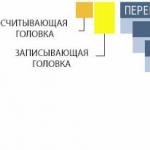
In RAID systems, to improve reliability and performance, combinations of three main mechanisms are used, each of which is well known separately: - the organization of “mirror” disks, i.e. complete duplication of stored information; - counting of control codes (parity, Hamming codes), allowing to recover information in case of failure; - distribution of information across different disks of the array in the same way as it is done when interleaving accesses to memory blocks (see interleave), which increases the possibility of parallel operation of disks during operations on stored information. When describing RAID, this technique is called "stripped disks", which literally means "striped disks", or simply "striped disks"..
Rice. 43. Partitioning disks into alternating blocks - “stripes”.
Initially, five types of disk arrays were defined, designated RAID 1 - RAID 5, differing in their features and performance. Each of these types, due to a certain redundancy of the information being written, provided increased fault tolerance compared to a single drive. In addition, an array of disks that does not have redundancy, but allows for increased performance (due to striping of accesses), has become often referred to as RAID 0.
The main types of RAID arrays can be briefly described as follows.
RAID 0. Typically, this type of array is defined as a group of striped disks with no parity and no data redundancy. The sizes of stripes (stripes, or blocks) can be large in a multi-user environment or small in a single-user system for sequential access to long records.
The organization of RAID 0 just corresponds to the one shown in Fig. 43. Write and read operations can be performed simultaneously on each drive. The minimum number of drives for RAID 0 is two.
This type is characterized by high performance and the most efficient use of disk space, however, the failure of one of the disks makes it impossible to work with the entire array.
RAID 1. This type of disk array (Fig. 44, a) is also known as a mirrored drive and is simply a pair of drives that duplicate stored data but appear to the computer as a single drive. And although striping is not performed within a single pair of mirrored disks, block striping can be organized for several RAID 1 arrays, which together form one large array of several mirrored disk pairs. This variant of the organization is called RAID 1 + 0. There is also a reverse variant.
All write operations are performed simultaneously to both disks of a mirrored pair so that the information in them is identical. But when reading, each of the disks in the pair can work independently, which allows two read operations to be performed simultaneously, thereby doubling the read performance. In this sense, RAID 1 provides the best performance of all disk array options.
RAID 2. In these disk arrays, blocks - data sectors are interleaved by a group of disks, some of which are used only for storing control information - ECC (error correcting codes) codes. But since all modern drives have built-in ECC control, RAID 2 does little compared to other types of RAID, and is now rarely used.
RAID 3. As in RAID 2, in this type of disk array (Fig. 44, b) blocks-sectors are interleaved across a group of disks, but one of the disks of the group is reserved for storing parity information. In the event of a drive failure, data recovery is carried out based on the calculation of the values of the "exclusive OR" (XOR) function from the data recorded on the remaining disks. Recordings usually occupy all disks (because the stripes are short), which increases the overall data transfer rate. Since each I/O operation requires access to each disk, a RAID 3 array can only serve one request at a time. Therefore, this type provides the best performance for a single user in a single-tasking environment with long writes. When working with short recordings, synchronization of the drive spindles is required to avoid performance degradation. In terms of its characteristics, RAID 3 is close to RAID 5 (see below).
RAID 4. This organization, shown in fig. 35, v) is similar to RAID 3, with the only difference being that it uses large blocks (stripes) so that records can be read from any drive in the array (except the drive that stores the parity codes). This allows you to combine read operations on different disks. Write operations always update the parity disk, so they cannot be merged. In general, this architecture has no particular advantages over other RAID options.
RAID 5. This type of disk array is similar to RAID 4, but the parity codes are not stored on a dedicated disk, but in blocks located alternately on all disks. This organization is even sometimes called an array with “rotating parity” (one can note some analogy with the assignment of interrupt lines for PCI bus slots or with the cyclic priority of the interrupt controller in x86 line processors). This distribution avoids the limitation of simultaneous writes due to the storage of parity codes on only one disk, which is typical for RAID 4. In fig. 44, G) shows an array consisting of four drives, with for every three data blocks there is one parity block (these blocks are shaded), the location of which for each triple of data blocks changes, moving cyclically through all four drives.
Read operations can be performed in parallel for all disks. Write operations that require two drives (for data and for parity) can usually also be combined, since the parity codes are distributed across all drives.
A comparison of various options for organizing disk arrays shows the following.
RAID 0 is the fastest and most efficient option, but it does not provide fault tolerance. It requires a minimum of 2 drives. Write and read operations can be performed simultaneously on each drive.
The RAID 1 architecture is most suitable for high performance, highly reliable applications, but also the most expensive. It is also the only option that is fault-tolerant if only two drives are used. Read operations can be performed simultaneously for each drive, write operations are always duplicated for a mirrored pair of drives.
The RAID 2 architecture is rarely used.
A RAID 3 disk array can be used to speed up data transfer and improve fault tolerance in a single-user environment with sequential access to long records. But it does not allow to combine operations and requires synchronization of rotation of drive spindles. It needs at least three drives: 2 for data and one for parity codes.
The RAID 4 architecture does not support concurrent operations and has no advantages over RAID 5.
RAID 5 is efficient, fault tolerant, and performs well. But performance during writes and in the event of a drive failure is worse than RAID 1. In particular, since the block of parity codes refers to the entire block being written, then if only part of it is written, you must first read the previously written data, then calculate the new values of the parity codes and only after that write new data (and parity). Rebuilding operations also take longer due to the need to generate parity codes. This type of RAID requires at least three drives.
In addition, based on the most common variants of RAID: 0, 1 and 5, so-called two-level architectures can be formed, which combine the principles of organizing various types of arrays. For example, multiple RAID arrays of the same type can be combined into one data array group or parity array.
Due to this two-level organization, it is possible to achieve the required balance between the increase in data storage reliability characteristic of RAID 1 and RAID 5 arrays and the high read speed inherent in striping blocks on disks in a RAID 0 array. Such two-level schemes are sometimes called RAID 0 + 1 or 10 and 0+5 or 50.
The operation of RAID arrays can be controlled not only by hardware, but also by software, the possibility of which is provided in some server versions of operating systems. Although it is clear that such an implementation will have significantly worse performance characteristics.
Making a request
Description of RAID arrays ( , )
Description RAID 0
High Performance Disk Array Without Fault Tolerance
Striped Disk Array without Fault Tolerance
RAID 0 is the fastest and least secure of all RAIDs. The data is divided into blocks in proportion to the number of disks, resulting in higher throughput. The high performance of this structure is ensured by parallel writing and the absence of redundant copying. The failure of any drive in the array results in the loss of all data. This level is called striping.
Advantages:
- · the highest productivity for the applications demanding intensive processing of input/output requests and data of large volume;
- ease of implementation;
- low cost per unit of volume.
Flaws:
- non-fail-safe solution;
- · A single disk failure results in the loss of all data in the array.
Description of RAID 1

Disk array with duplication or mirroring
Duplexing & Mirroring
RAID 1 - mirroring - mirror image of two disks. The redundancy of the structure of this array ensures its high fault tolerance. The array is characterized by high cost and low performance.
Advantages:
- ease of implementation;
- ease of array recovery in case of failure (copying);
- sufficiently high performance for applications with high request intensity.
Flaws:
- high cost per volume unit - 100% redundancy;
- low data transfer rate.
Description of RAID 2

Fault Tolerant Disk Array Using Hamming Code
Hamming Code ECC
RAID 2 uses Hamming Code ECC. The codes allow you to correct single and detect double faults.
Advantages:
- fast error correction ("on the fly");
- · very high speed of data transmission of large volumes;
- · with an increase in the number of disks, the overhead costs are reduced;
- rather simple implementation.
Flaws:
- high cost with a small number of disks;
- low query processing speed (not suitable for transaction-oriented systems).
Description of RAID 3

Fault-tolerant array with parallel data transfer and parity
Parallel Transfer Disks with Parity
RAID 3 - data is stored on the principle of striping at the level of bytes with a checksum (CS) on one of the disks. The array does not have the problem of some redundancy as in RAID 2. The checksum disks used in RAID 2 are needed to detect mischarging. However, most modern controllers are able to detect when a disk has failed by using special signals or additional encoding of information written to the disk and used to correct random failures.
Advantages:
- very high data transfer rate;
- Disk failure has little effect on the speed of the array;
- low overhead for the implementation of redundancy.
Flaws:
- difficult implementation;
- low performance at high intensity of requests for data of small volume.
RAID technology allows you to combine several physical disk devices (hard disks or partitions on them) into a disk array. The disks included in the array are managed centrally and are presented in the system as one logical device, suitable for organizing a single file system on it.
There are two ways to implement RAID:
- hardware;
- program.
A hardware disk array consists of several hard disk drives managed by a dedicated RAID controller board.
Pros of hardware RAID:
- higher reliability (compared to software);
- minimum load on the processor and system bus;
Software RAID is implemented using a special driver. Disk partitions are organized into a software array, which can occupy both the entire disk and its part, and management is carried out through special utilities.
Benefits of software RAID:
- higher data processing speed;
- independence from data formats on the disk (compatibility with different types and sizes of partitions);
- savings on the purchase of additional equipment.
RAID levels
There are several types of RAID arrays, the so-called levels.
RAID0
To create an array of this level, you need at least two disks of the same size. Recording is carried out according to the principle alternation: data is divided into data portions of the same size, and distributed one by one across all disks included in the array. Since recording is carried out on all disks, if one of them fails, the all data stored in the array. This is the price of choosing to increase the speed of working with data: writing and reading on different disks occurs in parallel and, accordingly, faster.
RAID1
Arrays of this level are built according to the principle mirroring, in which all data recorded on one disk is duplicated on another. To create such an array, two or more disks of the same size are required. Redundancy provides fault tolerance of the array: in case of failure of one of the disks, the data on the other remains intact. The payoff for reliability is the actual halving of disk space. The read and write speed remains at the level of a conventional hard drive.
RAID4
RAID4 arrays implement the principle parity, which combines striping and mirroring technologies. One of the three (or more) disks is used to store parity information in the form of blocks with checksums of data blocks sequentially distributed on the remaining disks (as in RAID0).
The advantages of this level are the fault tolerance of the RAID1 level with less redundancy (no matter how many disks the array consists of, only one of them is used for control information). If one of the disks fails, the lost data can be recovered from the control blocks, and if the array has a spare disk, data reconstruction will start automatically. The obvious disadvantage, however, is the reduction in write speed, since the parity information has to be calculated with each new write to the disk.
RAID5
This level is similar to RAID4, except that blocks with parity information are not located on a separate disk, but are evenly distributed across all disks of the array along with data blocks. As a result, there is an increase in the speed of working with data and high fault tolerance.