The carburetor should be adjusted only after checking the general technical serviceability of the engine and the power supply system, the serviceability and correctness of the ignition system adjustments.
To pre-adjust the quality of the mixture idle move fully screw in screw 2 (Figure 18), then unscrew it by one turn. When the screw is turned clockwise, the mixture is enriched, counterclockwise, it is leaner.
Idle adjustment screw
Idle mixture adjustment screw
The idle speed adjustment is carried out first preliminary (with the engine turned off), then finally.
For preliminary adjustment, unscrew screw 1 until it comes into contact with the throttle. Tighten screw 1 until it touches the throttle, then, continuing to tighten the screw, ensure a gap of 1.8 ... 2.0 mm (Figure 19) between the end of the throttle and the surface of the carburetor outlet (engine side). For final idle adjustment, start the engine and let it warm up. Then, turning screw 2 in both directions within approximately 0.5 turn from the preset position, set it to the position that provides the highest engine speed. After that, adjust the idle speed to the minimum stable by turning screw 1 counterclockwise to decrease the speed.
ATTENTION
During further operation, it is not recommended to change the position of screw 2. Use screw 1 to adjust the idle speed.
|
ATTENTION |
|
MIKUNI VM34-619 carburetors are adjusted at the factory, the quality screw is turned back one turn, the needle lock is installed in the third groove from the top. When the air temperature is above 0OWe recommend installing the needle retainer in the second groove from the top, the idle screw - 1.5 turns. Self-adjustment of carburetors is not allowed. |
|
|

Figure 19 - Checking clearance
Adjustment of the quality of the mixture for the operating conditions of the engine, depending on climatic and other factors, is carried out by rearranging the metering throttle needle in the needle lock. When the needle is raised, the mixture is enriched, when it is lowered, it is leaner.
Changing the carburetor adjustment at low negative ambient temperatures
At ambient temperatures below minus 20°C, the carburetor adjustment must be changed. Otherwise, engine damage may result.
Installing a kit of parts to adapt the snowmobile to high altitude conditions.If you live or operate your snowmobile at altitudes above 1200 m (1200 m), you must equip your snowmobile with a special carburetor kit to adapt it to high altitude conditions. To do this, contact an authorized dealer.
ATTENTION
Do not change the factory carburetor settings if the snowmobile is operated at altitudes up to 1200 m above sea level.
Transmission Maintenance
Maintenance snowmobile transmission consists in making adjustments, checking the condition of the variator belt, tightening threaded connections, cleaning external surfaces from dirt and lubricating work.
Variator maintenance.For reliable operation of the variator and increasing the durability of the variator belt, the relative position of the driving and driven pulleys is important.
The size indicated in Figure 4 (55 ± 0.5 mm) from the end of the fixed drive disc to the end of the fixed driven drive, check with two rulers. If necessary, make adjustments as follows:
loosen the bolts securing the engine to the sub-engine base;
by moving the engine, set the required size, parallelism of the engine shaft and the drive shaft of the reverse box;
tighten the engine mounting bolts.
Check the condition of the drive belt. If the belt is badly worn
(belt width less than 30mm) or damaged, replace the belt.
To remove the variator belt:
Mount the belt only after holding it for a day at a temperature of plus 15 ... 25 ° C or at least 30 minutes at a temperature of plus 50 ° C.
Installation of the belt in the field is allowed only after it has been kept in the engine compartment for at least 15 minutes after the engine has warmed up.
turn on any gear of the reverse box;
remove the variator cover;
spread the disks of the driven pulley and remove the belt over the edge of the fixed disk;
remove the belt from the drive pulley.
Install the belt in reverse order. Make sure the markings on the outside of the belt are not upside down when viewed from the port side of the snowmobile. This ensures the maximum resource of the variator belt.
Notes:
To lubricate the drive pulley of the variator and the drive shaft of the reverse box:
remove the variator cover;
unscrew the bolt, remove the washer, cover and movable disk of the centrifugal regulator;
disassemble the weights by unscrewing the nuts securing the axles and weights, and wash the axles and rollers;
unscrew the bolt from the drive shaft of the reverse box and remove the two washers;
using a puller, remove the fixed disk;
remove the variator belt;
remove the retaining ring, half ring and movable disk of the driven pulley;
lubricate according to table 4 and install the removed parts in reverse order.
Attention!
Lubrication on the working surfaces of the variator disks is not allowed.
Reverse box maintenanceincludes checking and adjusting the chain tension, checking the level and changing the oil in the crankcase, eliminating oil leakage through the crankcase connector.
To adjust chain tension:
unscrew the fixing bolt of the tensioner and remove the rubber cover of the viewing window;
put the control lever of the reverse box in the "Forward" position
by turning the drive pulley disk counterclockwise until it stops
tension the chain, turning the disk clockwise - relax. The difference between the indicated positions of the chain should be 1 ... 5 mm (see Fig. 20);
by rotating the eccentric axis of the tension sprocket, set the required chain deflection. Fix the found position of the axis with a bolt.
Chain tension can be checked by looking at the backlash of the variator driven pulley. Engage forward gear. Measured by outside diameter

of the driven pulley, the play should be 20 ... 40 mm.
To flush the reverse box, do the following:
unscrew the crankcase drain plug and drain the oil;
put the plug back in place;
pour into the crankcase through the hole in the cover 1 liter of a flushing mixture consisting of 75% gasoline and 25% MK-8 oil;
start the engine and, with reverse switching, break in the snowmobile for 10 ... 15 minutes;
Rice. 20 - Adjusting the tension of the chain of the reverse box
after running in, drain the flushing mixture and fill the reverser box with fresh oil in a volume of 350 cm through the hole in the lid3 .
Check the oil level in the reverse box using a special
probe through the viewing window. When checking, the bend of the probe should touch the lower edge of the viewing window. In this case, the oil level should be between the control marks on the dipstick.
However, a number of shortcomings of engineers in this model were identified. Modern conditions required the improvement and modernization of this device. Therefore, in the 90s of the twentieth century, the K 65 model (carburetor) was created. This device is externally similar to the previous device. But its content is very different from it. This is reflected in the principle of operation, regulation and design of the K 65 variety.
Carburetor device K 65
To adjust the K 65 carburetor, you first need to familiarize yourself with its device. The supply and maintenance of the fuel level occurs according to the following scheme. Through the fitting, fuel is supplied to the valve with elastic. This block relies on a tongue that communicates with the floats. They are made of plastic and are interconnected. The floats circulate freely along the axis.
If there is more fuel, its excess is discharged through the drain hole from the float chamber. Model K 65 (carburetor) heats up during operation. At the same time, so that the pressure in the chamber does not increase, it is connected to the imbalance channel.
The next system to be considered in the K 65 carburetor circuit is the dosing device.
Dosing system
The components of the dosing system are the main fuel jet, atomizer, air supply channel and throttle needle.
The whole process of the system works according to the following scheme. From the float chamber, fuel enters the atomizer through the main jet. Under the action of liquefaction, it rises along the gap between the throttle needle and the atomizer. At the exit from it, the fuel is mixed with air, which entered through the hole in the atomizer housing through the channel.
The K 65 carburetor has the following engine control system. The throttle needle is set to one of five positions. This makes the engine run at medium speeds. But at the highest power, it should be taken into account when setting up that the carburetor of the K 65 model determines the fuel consumption by the throughput of the main fuel jet.
A lock washer is installed under the fuel pipe. It secures the atomizer.
Idle system
Another important system that must be considered when adjusting the K 65 carburetor is the idle device.

The presented system consists of a fuel pipe, an air channel, an idle hole, screws for the quality and quantity of the mixture, and a via.
When the motor is running at low speeds, an emulsion is formed. This happens by raising the fuel through the tube under the action of vacuum in the mixing chamber. The fuel is combined with air, which enters through the channel. The K 65 carburetor assumes that the emulsion will exit at low speeds only through the idle hole.
With an increase in speed, the vacuum in the hole zone increases. The same emulsion also begins to flow through it. So the fuel supply increases with an increase in engine speed.
Engine starting and heating system
In search of an answer to the question of how to adjust the K 65 carburetor, you should familiarize yourself with the device for starting and heating the engine.

On carburetors K 65S and K 65V, a starting device with an autonomous drive is installed, on K 65G and K 65Zh - with a cable drive (found in Dnepr and Ural motorcycles), and for K 65I, K 65D - a corrector-heater (often used in mopeds brand "IZH").
A self-powered starter consists of a plunger, a starting device, a needle, a protective cap, channels, a control rod, a fuel well and holes. The normal position of the device is considered closed.
The cable starter is very similar to the previous version, except for the presence of a rod. The position of the plunger is regulated by a cable.
The corrector-enricher is characterized by such a functioning system in which fuel enters the starting device from the float chamber. Fuel consumption is limited by the jet. Such a device often has a Soviet K 65 carburetor. IZH can serve as an example of such motorcycles.
Installation and setup
Before adjusting a new K 65 carburetor, it must be installed and adjusted.

First you need to remove the carburetor cover. The throttle spring holds the needle through the lock. It has one round and two shaped holes. A round slot located in the center serves to attach the gas cable. The T-shaped hole is necessary for attaching the screw rod.
Having installed the carburetor on the engine, a cable is connected to the throttle, the cover is fixed.
Raise the throttle with the throttle handle and check if the diffuser opens completely. These actions should be performed several times. The diffuser should open and close freely without jamming.
If the K 65 device (carburetor) has a corrector, it should be removed as an assembly and the cable connected to the piston. After that, you should install the node in place.
The screw must be tightened to the stop, then loosen it by 0.5-1.5 turns. The fuel hose is attached to the fitting. Fuel must not leak at the joints.
Then the peak starter turns and spins crankshaft for 3 turns. The ignition is turned on and the start is made. After warming up, the starting device or corrector can be turned off.
Fuel level adjustment
Carburetor adjustment K 65 begins with setting the fuel level. To do this, turn the device over and remove the bottom of the float chamber. Next, the distance from the connector to the line that divides the float into two parts is replaced.

This distance is usually 13 mm with a possible deviation of 1.5 mm on both sides.
If the size on the carburetor does not fit into this framework, you should bend the float tongue in the right direction.
It happens that the K 65 carburetor is set up correctly, but it starts to “overflow”. This means that the float has leaked.
It is easy to test this theory. You need to draw warm water into the bath and immerse the float in it for a minute or longer. If bubbles appear, then the float is defective.
Mix enrichment adjustment
Before starting the adjustment, whether it is the carburetor of the K 65 model of the Ural, Dnepr motorcycle, Buran snowmobile or other vehicles, the engine should be warmed up.
Then the minimum stable ones are installed. For this, the throttle should be lowered with a screw. After you need to increase the number of revolutions to the maximum possible. The screw is rotated in one direction or another.
Slowly increase and decrease the speed again. This should be done 2-3 times.
After the manipulations, you should check how the engine reacts to the position of the throttle. To understand how to set up a K 65 carburetor, you must determine the required level of enrichment of the fuel mixture for the engine.
For this, an experiment is carried out. The throttle opens abruptly. If at the same time the engine stalls, then the mixture should be enriched. To do this, tighten the mixture quality screw 1/4 or 1/2 turn.
A stalling engine with a sharp closing of the throttle indicates the need to make the mixture leaner. In this case, the mixture quality screw must be rebuilt by 1/4-1/2 turn.
Adjusting the quality of the mixture in operation
The K 65 carburetor is adjusted under operating conditions by moving the dispenser needle relative to the lock. This must be done in a specific order.
The dosing needle is set to the middle position. To lean the mixture, the lock is shifted upwards. In this case, the gap between the dispenser cone and the wall of the atomizer becomes smaller.
Moving the lock down will enrich the fuel mixture.
The signal for the need for adjustment will be the color of the spark plug electrode insulation. You should pay attention to it after 30 km of run. Under normal operating conditions, its whitish color indicates the poverty of the mixture. A dark brown insulator with traces of soot indicates the need to lean the mixture.
Adjusting the carburetor of the motorcycle "Ural"
For an example of adjusting the K 65 carburetor, you can consider this procedure on a Ural motorcycle.

First you need to remove the air intake. Next, use a flat screwdriver to unscrew the screws. The carburetor K 65 of the Ural motorcycle requires the screw to be unscrewed by 1 turn.
After that, you need to set the play on the cables. It should be the same and equal to about 3 mm.
Warming up the engine, they begin to tighten the idle screw to the minimum stable speed. Then, using the mixture quality screw, you should find the maximum speed. The procedure is repeated twice. The carburetor is set.
Carburetor Timing
After tuning, the K 65 ("Ural") carburetor must be synchronized. It is convenient to do this with a tachometer. In the absence of such equipment, synchronization can be performed using the speedometer.
To do this, the motorcycle is placed on a stand and the engine is started. 4th gear is exposed. Remove the cap from one of the candles and bring the speedometer to 50 km / h. The gas handle is fixed with a bolt.
One cylinder alternately turns on and the other turns off. The length of the cables is adjustable with fittings. At the same time, they achieve the same indicator of the speedometer.
When removed, the spark plug cap must be grounded, shorted to the mass of the motorcycle. In this way, the Ural carburetor can be adjusted.
Adjusting the carburetor K 65 motorcycle "IZH"
A simpler adjustment is performed for the IZH motorcycle, which has a corrector-enricher.

First, the engine warms up. Then low, but stable engine speeds are set. To do this, turn the screw that adjusts the position of the throttle.
Then smoothly increase the speed to maximum with the help of the idle screw. The procedure is repeated 4-5 times. At the same time, the engine speed is gradually reduced. After that, the correctness of the setting is checked by sharp jerks in opening and closing the throttle.
The engine should not stall and make sharp jerks.
For this model of carburetor, it is also possible to make adjustments in the operating mode by moving the metering needle up to enrich the mixture and down for the opposite effect.
This type of setup is one of the easiest. Therefore, everyone can perform all the actions according to the instructions on their own.
Having become acquainted with the device, the method of installing and configuring such a motorcycle element as K 65 (carburetor), each user can independently regulate its operation. For every type vehicle you should follow your technology for setting up and checking the operation of the carburetor. The durability of the vehicle depends on the correctness of the actions.
In this article you will find the answer to the question of how to adjust the Mikuni carburetor on a snowmobile.
The information below is fully applicable both for the RMZ-500A engine and for the two carburetors of the RMZ-500V engine.
The process of forming a gaseous fuel mixture from fuel and air is called carburation.
transformation liquid fuel to gaseous can occur by evaporation or atomization. And the device with which this happens is called a carburetor. The carburetor (carburetors) of the Mikuni company is installed on the taiga snowmobile.
Using the marking on the body, you can identify the device, so according to the inscription 34-560 you can determine the diameter of the diffuser - 34 mm., By the first two digits.

To get a general idea of what parts the carburetor consists of, you can see the figure below:

In the following text of the article, we will refer to the numbers on the details in this image. shared device and the principle of operation of Mikuni carburetors can be found in the article "".
Before installing and adjusting on the snowmobile, inspect the carburetor for damage. If the device is dirty, it must be cleaned. The carburetor assembly can be cleaned with solvents or special fluids. There are several recommendations for doing such work:
- do not wash rubber parts, rings and float with solvent or cleaner, these substances may be unacceptable for the materials of these parts;
- the body and jets are washed with a cleaner;
- filter 15 is checked, if necessary, cleaned or replaced;
- we check the shut-off fuel needle valve 16, if a malfunction is suspected, we replace it with a kit along with a socket;
- check the throttle valve 5 for wear, change if necessary;
- inspect the idle screw 7, if it is bent, we also change it;
- we check the float 12 for the presence of fuel in it, it should be absent, we also examine it for damage or cracks, the float should move freely without jamming, we change it if necessary.
The metering needle 3 plays an important role in shaping the composition of the fuel mixture in the main engine operating modes, so it is worth saying a few words about this carburetor element.
The position of the metering needle 3 is set using 5 grooves in the upper part, and is regulated thanks to the lock 2. The uppermost groove corresponds to the leanest mixture (the needle is maximally lowered, the amount of fuel is reduced), and the lower groove corresponds to the richest mixture (the needle is maximally raised, fuel is supplied more).

In addition, the dosing needles are marked. For example 6DH8-4, the last digit indicates the recommended needle position, 4 is the number of the groove in the lock, if counted from the top of the needle.
Carburetor float adjustment
The position of the float determines the level of fuel in the float chamber, at the same time, the operation of the engine as a whole in different modes, and of course its efficiency. To check the float mechanism, it is necessary to remove the body of the float chamber 11. We examine the bracket 9 of the float, it must be symmetrical and undeformed. We turn the carburetor body upside down with a float and install it on a flat vertical surface. It is necessary to set the height H from the surface of the housing to the upper edge of the float bracket.

For this purpose, we use a ruler, which must be placed perpendicular to the surface of the body, parallel to the axis of the float and in the same plane with the axis passing along the channel of the main fuel jet.
The float is adjustable by bending tab 1 in the figure below.

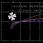
For a better understanding of the operation of the carburetor, in the figure below you can see which metering systems are included in the work as the throttle is opened.

Mikuni snowmobile carburetor pre-adjustment
Preliminary adjustment of the carburetor is carried out with the engine not running.

1. Completely, but not tightly, tighten the idle mixture quality screw, after which it is necessary to unscrew for VM 34-619 carburetors with an idle jet (HHH) 55 - by 2 turns, for VM 34-619 with HHH 40 - 1.0 ... 1.5 turnover.
2. Loosen the throttle cable jam nut on the carburetor, and back out the idle speed screw completely so that it does not come into contact with the throttle. Use the adjustment screw to remove the slack (play) of the cable. Check full throttle opening. By pressing the throttle lever all the way, check that the throttle opens completely or a maximum of 1 mm below the edge of the diffuser on the engine side, if necessary, you can adjust it with a cable screw.

Pay attention to the gap between the carburetor cover and the throttle, it must be present. The absence of this gap threatens to damage the throttle cable or carburetor parts.

3. Secure the throttle cable screw with the locknut.
If the engine is equipped with two carburetors, check the synchronous opening of the throttle valves on both carburetors, adjust if necessary.
4. Let us now adjust the amount of opening of the throttle valve, the distance between the diffuser and the edge of the throttle should be 1.5 ... 1.6 mm. Use for this purpose a drill shank or a piece of wire of the required diameter.

Final carburetor adjustment
The final adjustment of the carburetor is carried out by checking the obtained adjustments on a running engine during trial runs. According to the manufacturer's recommendations, do not adjust the engine idle speed with the idle mixture quality screw, this can lead to engine failure. At idle, the speed is controlled by the idle speed screw (quantity screw).
Mikuni carburetor adjustment on a taiga snowmobile is carried out according to the algorithm:
- Clean the spark plug(s) from carbon deposits and set the gap between the electrodes to 0.7…0.8 mm.
- Make a test run of 3-5 km. At a speed of 40 ... 50 km / h.
- Shut off the engine, avoiding idling.
- Check the carbon deposits on the spark plugs, they should be dark brown.
- If the plugs are wet or black soot, the mixture is too rich, move the metering needle to the second groove from the top and repeat steps 1 to 4.
It is also possible to adjust the idle mixture quality screw. But do not back out this screw more than 2.5 turns.
The atomization, evaporation and mixing of fuel with air is called carburation, and the device by which this is achieved is called a carburettor.
The transformation of fuel from a liquid state into a vapor (gaseous) is carried out different ways: by spraying fuel, blowing small droplets of fuel with air, lowering the air pressure in the place where fuel is sprayed and evaporated, heating fuel or using easily evaporating fuel.
A number of requirements are imposed on the combustible mixture obtained by these methods. It should be such that the fuel was in a vapor state by the time of its ignition, the composition of the fuel inside the cylinder was homogeneous, the composition of the mixture in all cylinders was the same, the combustible mixture ensured the most advantageous flow of the working process in this mode.
Withdrawal
Remove the intake silencer.
Disconnect the fuel supply line.
Unscrew the cover 1 of the carburetor, then pull the throttle 5 out of the carburetor.
Disconnect the cable from the throttle.
Loosen the clamps on the intake manifold rubber coupling, then remove the carburetor from the engine.
Cleaning and controlThe assembled carburetor should be cleaned with common solvents and dried with compressed air before disassembly.
The carburetor body and jets must be cleaned with cleaners.
Check filter 15 for clogging. Clean or replace if required.
Check the condition of the needle valve 16. If it is defective, the needle and valve seat must be replaced as a set.
Check throttle for wear. Replace it if necessary.
Check that the idle speed screw 7 is not bent. Replace if necessary.
Check if there is fuel in float 12, replace if necessary.
Check the float for cracks or other damage affecting free movement; replace if necessary.
IdentificationAll carburetors have an identification marking on the body.
|
|

Identification
Example 34-560 - the first two digits indicate the diffuser diameter in mm.
Disassembly and assembly
Remove the screws from the stop plate 4 to remove the needle 3.
The position of the needle in the throttle is adjusted by means of the needle lock 2 inserted into one of the five grooves located on the top of the needle. Position 1 (at the top) corresponds to the leanest combustible mixture, 5 (at the bottom) - to the most enriched.
NOTE: The last digit in the needle identification number gives the recommended needle lock position from the top of the needle.

Castle position

Carburetor float adjustment
The correct position of the float in the float chamber of the carburetor is essential for maximum engine efficiency. To check that the float position is correctly adjusted, proceed as follows:
remove the float chamber 11 and the gasket from the carburetor
make sure float bracket 9 is symmetrical - not deformed
with the carburetor positioned upside down on a flat surface, measure the height H between the surface of the body and the top edge of the contact foot. Hold the ruler vertically, parallel to the axis of the float and in the same plane as the axis of the main jet opening.
For height adjustment H
bend the float contact tab until the desired H value is reached (see section 10-01).
Illustration of the operation of the metering elements depending on the throttle lift
NOTE: Refer to the "Technical Data" section and the "Spark plugs" section for a thorough study.
InstallationInstall the carburetor in the reverse order of the removal procedure. Before setting the carburetor, check the condition of the body and the throttle cable (triple cable).
Install the worm-drive clamps so that their tightening bolts are misaligned - not aligned.
Install the throttle cable into the needle stop plate
NOTE: Do not block the hole in the throttle when installing the needle stop plate. This is an important condition that allows the carburetor throttle well to be breathed.
Make sure you have plastic needle seals.
Installing the needle in the choke
Needle Lock
Needle stop plate
Screw
Needle
plastic seal
Throttle
Throttle cable
Carburetor adjustment
1. Idle screw
Idle mixture quality screw (air screw)
Preliminary adjustment of the carburetor with the engine not running
Fully, but not tight, tighten the idle mixture screw 6, and then loosen it in accordance with the data given in section 10-01. By turning the screw clockwise, we enrich the mixture and, conversely, by turning it counterclockwise, we deplete.
Completely turn out the idle speed screw 7 - it should not come into contact with the throttle. Loosen the locknut of the throttle cable adjusting screw, select the cable play.
Press the throttle lever all the way down - the lower edge of the throttle should be flush with the top of the diffuser or no more than 1 mm lower (engine side). If necessary, turn the adjusting screw to adjust the throttle position.
Lid
Gap
Throttle
Tighten the locknut after adjustment is complete.
When adjusting the carburetors of a two-carburetor engine, pay attention to the synchronism of the opening of the throttle valves - both dampers must open simultaneously. If necessary, adjust the position of the throttles with the adjusting screws of the triple cable.
Using the idle speed screw, set the gap between the lower edge of the throttle (engine side) and the diffuser to 1.5 ... 1.6 mm. (When setting the gap, use a wire or drill of the correct diameter).
|
|

Drill bit used as gauge
Final adjustment of the carburetor with the engine running
Start the engine and let it warm up, then adjust the idle speed (See Section 10-01). by turning the idle speed screw 7 (both screws in the same way for two carbureted engines) clockwise to increase engine speed, or counterclockwise to decrease them.
Fuel Corrector Plunger AdjustmentSet the lever 17 of the fuel corrector plunger to the “Open” position
Fuel corrector plunger lever in the "Open" position
Use small tool diameter for VM 32 carburettor.
Insert the plunger tool into the air passage of the carburetor fuel corrector. The tool stop must be within 1 mm of the recess wall.
View from the intake silencer
Tool stop within 1 mm of the recess wall
If the tip of the tool does not fit under plunger 18, adjust the plunger position as follows.
Make sure the plunger lever is in the "Open" position.
Lift up the protective cap and loosen the fuel equalizer cable adjusting screw locknut as shown in the following figure.
|
|

Lift up the protective cap
Loosen locknut
Turn the fuel trim cable adjustment nut until the tool is properly seated under the plunger.
NOTE: Light pressure is required to insert the tool under the plunger.
Check for correct adjustment set lever 17 to the close and open positions and ensure that the tool is properly seated under the plunger only when the lever is in the fully open position. Set the lever to the "close" position and check for play in the fuel corrector cable.
Through fitting 20, it enters the fuel valve 15, which is equipped with an elastic locking washer. The valve rests on a tongue 18 connected to plastic floats 17, which are interconnected and freely rotate on the axis 16.
If for some reason the fuel level rises, its excess is discharged from the float chamber through the drain hole 32. So that the pressure in the float chamber does not increase when heated, it is connected to the atmosphere by an unbalancing channel 31. The main metering system consists of atomizer 5, the main fuel jet 6, throttle needles 7 and air supply channel 8. Fuel from the float chamber through the main fuel jet 6 enters the atomizer 5, rising under the action of vacuum through the gap between the atomizer and the throttle needle 7. channel 8 through the hole in the atomizer housing.The throttle needle ensures engine operation in medium modes and can be set to one of five positions.In the highest power modes, fuel consumption is determined mainly by the throughput of the main fuel jet.Reliable fastening of the atomizer is ensured by a lock washer 14 installed under fuel ivy tube 9. The idle system consists, in turn, of a fuel tube 9, an air channel 10, mixture quality screws 11 and mixture quantity 27, an idle hole 12 and a via hole 13. When the engine is idling under the action of vacuum in In the mixing chamber behind the throttle, the fuel rises through tube 9 and mixes with air entering through channel 10. The resulting emulsion, with a slight opening of the throttle (at low speeds), exits only through hole 12. With further rise of the throttle and increasing speed, the vacuum in the area of hole 13 increases and emulsion also begins to flow through it. Thus, the fuel supply increases as the number of revolutions increases. The main system for starting and warming up the engine. Not carburetors of different modifications are applied different systems enrichment devices: on K65S and K65V - a starting device with an autonomous drive; on K65G and K65Zh - with a cable drive; on K65I and K65D - corrector-enricher. Let's take a look at them in that order. The starting device with an independent drive consists of a plunger 37, a guide 35, a return spring 36, a needle 39 of the starting device, a sealing gum 38, a protective cap 29, a control rod 40, as well as channels 33 and 34, a fuel well A and an opening 41. Normal the position of the device is closed. With this needle 39 s rubber band 38 blocks the fuel channel, and side surface plunger 37 - channels 33 and 34. To turn on the starting device, you need to lift the rod 40 up and turn it about 90 ". In this case, the extrusion on the rod will come out of the grooves of the guide 35 and will be fixed on its upper end. The plunger will rise, opening channels 33 and 34 and fuel channel 48. Under the action of vacuum, fuel from well A will fall into the cavity under the plunger, mix with air and be fed into the mixing chamber in the form of an emulsion. The volume of fuel in the well is sufficient for a high single supply at the time of start. the fuel in the well decreases and the composition of the mixture becomes poorer.To turn off the starting device, it is necessary, of course, to turn the rod back by about 90 °, after which the plunger will return to its original position under the action of the return spring 36. The starting device is protected from dust and dirt by a rubber cap, put on the spring guide 35. The starting device with a cable drive is similar to that described - but it does not have a stem 40, and the position plunger 37 is regulated by a cable led to the lever. The corrector-enricher differs in that the fuel enters it directly from the float chamber (there is no fuel well A). Fuel consumption is limited by jet 43. When the plunger is fully raised, the maximum enrichment of the mixture is achieved, which is necessary to start the engine. As the plunger is lowered, the mixture becomes more and more lean as the gap between the needle 42 and the channel wall decreases. When the plunger is completely lowered, the needle with sealing rubber 38 closes the fuel channel 48. An additional starting device (float sinker) is used at air temperatures from + 5 "C and below. Its use does not need explanations. Having considered the device and the principle of operation of individual systems, we right now to move on to issues of operation and adjustments.Before installing the carburetor, you need to remove its cover 2 with the throttle assembly.The cover is a rather complex subassembly, on which the throttle lift screw 27, guide 28, gasket 26, throttle lift limiter 30, throttle 21 and its spring 24, protective cap 29. The screw 27 is connected to the throttle by a rod. The throttle spring 24 simultaneously holds the needle 7 through the lock 22. The U-shaped brass throttle has two shaped holes and one round. The latter, located in the center, serves to installation and fastening of the needle, shaped on the side of the cutout - for fastening the gas cable, and T-shaped - for attaching propeller thrust 27. A radial cutout on the throttle wall, facing the air filter, provides the necessary vacuum in the atomizer zone. Inside the cover there is a limiter 30 - it is recommended to remove it after the break-in is completed. After installing the carburetor on the engine, you need to attach a cable to the throttle and fix the cover on the carburetor. After that, use the throttle handle to raise the throttle and check if it fully opens the diffuser. Do this a few times to make sure the throttle doesn't stick in any position and that the diffuser closes and opens completely. Raise the throttle with screw 27 to such a position that a 2-3 mm gap appears between its lower edge and the diffuser generatrix. If the carburetor has a trigger or corrector, you need to unscrew part 35, remove the corrector assembly and attach the cable to piston 27, then install the assembly in place. Adjust the position of the stops 28 of the shells of the throttle and corrector drive cables (if the latter is available) so that they have a free play of about 2-3 mm (this is done so that the position of the throttle or corrector does not change when the steering wheel is turned). Tighten the screw 11 until it stops, and then unscrew it by 0.5-1.5 turns. Attach the fuel hose to the union 20. Make sure that the fuel does not leak at the connection points, and open the starting device or corrector. If, due to weather conditions or the individual characteristics of the engine, it is necessary to use a float damper, it is better to do this with the throttle fully open at the same time, then the reception efficiency increases. Gently pressing the kick starter, turn the crankshaft 2-3 turns, turn on the ignition and start vigorously. After starting and warming up the engine, the starting device or corrector must be turned off. In conclusion, let's talk a little about carburetor adjustments - every motorcyclist has to deal with them from time to time. It is more expedient to start with setting the fuel level. To do this, turn the carburetor over, remove the bottom of the float chamber and measure the distance from the connector plane to the line dividing the float in half (a trace from the mold connector). This distance should be 13(+1.5/-1.5) mm. If on your carburetor the size does not fall within these limits, you need to carefully bend the tongue 18 of the float in one direction or another. In passing one more remark. If during operation the carburetor suddenly begins to "overflow", you need to check if the float has leaked. To do this, it should be immersed for at least a minute in a bath with hot water. Bubbles will appear - the float is thin, no - everything is in order. Before starting the adjustments, which will be discussed later, the engine must be warmed up. After that, lowering the throttle with screw 27, set the minimum stable idle speed, and then, slowly turning screw 11 in one direction or another, achieve an increase in speed to the maximum possible. Again with screw 27 try to reduce them, and then with screw 11 raise as far as possible. These operations sometimes have to be repeated 2-3 times. Now check how the engine reacts to the throttle. If, when the throttle is suddenly opened, it stalls, tighten the mixture quality screw 11 by 1 / 4-1 / 2 turns (the mixture will be enriched in this case); if the engine, on the contrary, stalls when the throttle is closed abruptly, screw 11 must be unscrewed by the same amount (the mixture will naturally become poorer). The quality of the mixture is adjusted in operating modes by moving the dosing needle 7 relative to the lock 22. You should start from its middle position. When the lock is moved up, the mixture becomes leaner (it is clear: the needle is lowered, and there is a smaller gap between its cone and the wall of the atomizer!), When the lock is moved down, it is enriched. The criterion for moving the needle can be the color of the insulator of the center electrode of the spark plug. If after a run of about 30-40 km in normal operating mode it has a whitish color, the mixture is poor and the needle must be raised at least one notch; if the insulator is dark brown, with traces of soot, the mixture must be made poorer by lowering the needle. Finally, if the motorcycle does not develop maximum speed, the main fuel jet should be replaced with a different one with a larger diameter calibrated hole.